Solder Joint Thermal Fatigue Test Chamber Per IPC 9701
IPC-9701 does not pass or fail a solder joint. It cycles the joint warm and cold until the solder cracks, then counts the cycles it took as a fatigue life. The chamber’s whole job is to make that count mean something.
IPC-9701 is the standard for one question the package tests leave out: how long the solder joints under a part last. It looks past the chip and its packaging to the small beads of solder that hold a surface-mount component onto its board, the joints that carry the part both mechanically and electrically. Those joints crack slowly, over years of a product warming and cooling through use, until one day a connection opens. IPC-9701 reproduces that slow grind in a chamber, cycling a board warm and cold again and again while it watches each joint, then turns the result into a number, a count of cycles to failure, the fatigue life of the joint.
What the standard measures
The subject is the joint, the small volume of solder between a component’s lead or pad and the board beneath it. IPC-9701 sets out how to thermally cycle those solder attachments and turn the result into a fatigue life, a number of cycles. Its concern stops at the joint. The chip sealed inside the package, the wires and the die, belong to other standards; this one watches only the solder that holds the whole part down to the board.
That solder is structural before it is electrical. It carries the part mechanically, holding it against every knock and vibration; it also carries the signal that makes the part useful. When the solder cracks, the connection it made is the connection lost, so a cracked joint can drop a part off the board entirely or break a single contact in a way that comes and goes with temperature. The joint is the one place a sound chip can still fail.
This focus sets IPC-9701 apart from the package tests. The JESD22 methods stress the die and its packaging, asking whether the part inside survives. IPC-9701 asks a different question one level out, at the board: do the joints that mount the part outlast the product they go into. A part can clear every package test and still fail here, at the solder, because the joint lives a harder mechanical life than the silicon it carries.
And the answer is a life, a count, never a grade. A qualification test ends in a pass or a fail; IPC-9701 ends in a count of cycles, the number the joints endured before they cracked. That count is the product, the thing the whole test exists to measure, which makes IPC-9701 a characterisation, a measurement of how long the joints hold rather than a verdict on whether they passed.
Why the joint cracks
The crack starts from a mismatch in how things grow. A component and the board it sits on are made of different materials, a ceramic or plastic body soldered onto a glass-epoxy laminate; each expands by its own amount as the assembly warms. The board grows more than a ceramic part, less than some plastic ones, so every change in temperature slides the part and the board a little against each other.

The solder joint takes up that difference. Sitting between the part and the board, the joint is sheared a little with every degree of change, stretched one way as the assembly heats, the other way as it cools. A single cycle does no harm. Thousands of them work the solder like a wire bent back and forth, until a crack starts at the worst-strained edge of the joint and creeps across it cycle by cycle.
Heat speeds the damage along. Solder is a soft metal that creeps under load, more so when it is hot, so the long dwell at the high temperature lets the strained joint relax and flow in a way that ages it faster than the cold end does. The crack that ends a joint’s life is the sum of all that slow working, a fatigue failure built one cycle at a time.
A life, not a verdict
What makes IPC-9701 unusual is the shape of what it returns. It returns a life, the count of cycles the joint survived before it cracked, a number that can be compared, plotted, then fed into a prediction. The test is built to measure a duration, never to judge a part against a single line.
That changes what the chamber is for. A pass-or-fail test runs until a part either survives a set number of cycles or does not. A life test runs until the joints actually fail, however long that takes, recording the cycle each one gives out. The chamber is not proving a part clears a bar; it is measuring how far past the bar the part can go, which asks more of the test than a simple pass ever would.
So the number has to be earned honestly. A fatigue life is only as good as the cycling that produced it, since the same joint cracks at a different cycle under a harsher or a gentler profile. The whole value of an IPC-9701 result rests on the chamber running the exact cycle the standard names, so the life it measures is the life the standard defines, a figure any other lab can stand beside its own.
The cycle that does the damage
The damage is done by the cycle, so the standard pins the cycle down. A test swings the board between a cold extreme and a hot one, holds it at each end long enough for the whole assembly to reach the temperature, then swings it back, over and over. The conditions are named by their extremes, picked to match where the product will live.
The range runs from mild to severe. A telecom condition cycles a gentle zero to a hundred degrees; a consumer one runs a wider minus forty to a hundred and twenty-five; an aerospace one stretches to minus fifty-five at the cold end. A harsher range fatigues the joints faster, so a lab picks the condition that stands for the product’s real service, then reads the life against it.
The dwell and the ramp are fixed as tightly as the extremes. The board holds about ten minutes at each end, long enough for the solder to reach the temperature and creep under it; the temperature changes no faster than about twenty degrees a minute, slow enough that the swing fatigues the joint, never shocks it. Every one of those numbers shapes the life the test will measure.
Cycled in one chamber
The cycling for IPC-9701 is done in a single chamber, the air around the board heated and cooled in place. The temperature ramps up and down within the one space at the measured pace the standard sets, so the board feels a gradual swing, never a sudden plunge. This is what marks fatigue cycling apart from thermal shock, where a part is thrown between two separate zones for the sharpest possible jolt.
The gentler ramp is the point of it. A fatigue life means the joints failed by the slow working the standard intends, so the single-chamber swing, ramped no faster than the rule allows, keeps the failure a fatigue one. A shock would crack the joints by a different mechanism, giving a life that answered the wrong question.
The two solders behave differently
Not all solder fatigues the same way. The older tin-lead solder and the lead-free tin-silver-copper alloys that replaced it creep and crack by different mechanisms, so a joint of one fails at a different cycle from a joint of the other under the same test. The alloy is part of what a fatigue life describes.
Lead-free solder is stiffer and less forgiving. It carries load harder than tin-lead, passing more strain into the joint than the older alloy would relax away, so its cracks can run by a different path and reach failure on a different schedule. A test that assumed tin-lead behaviour would misread a lead-free joint, which is one reason the alloy is named alongside the result.
So an IPC-9701 result names its solder. A fatigue life belongs to a particular alloy on a particular board under a particular cycle, the three pinned together. Comparing a lead-free life to a tin-lead one tells little unless everything else was held the same, so the test reports the alloy as plainly as it reports the cycle count.
Catching the crack: the daisy chain
Reading the exact cycle a joint cracks asks for a clever bit of wiring. The parts on the test board are daisy-chain coupons: their pads are linked in a continuous loop that runs the current in one joint and out the next, so a whole row of joints reads as a single electrical path. A break anywhere in that path shows up as a jump in its resistance.
A monitor watches that resistance through the whole test. As the board cycles, an instrument reads the resistance of each chain continuously, logging the moment it rises. A crack starting in a joint pinches the path, nudging the resistance up; a crack opening fully spikes it. The monitor catches the cycle it happens on, so the test knows the life of each chain to the cycle.
The standard sets a clear line for failure. A joint counts as failed at the first time its chain reads twenty percent above its starting resistance, confirmed across five or more consecutive scans so a single noisy reading does not trip it. That rule turns a gradual, noisy crack into a definite cycle number, the one event the whole test is built to timestamp.
What the test returns
The answer is a cycle count, the life the joint reached.
From a count to a curve
One joint’s life is a single data point. A test cycles many samples at once, often thirty or more, since solder fatigue scatters and one part’s life means little on its own. The lives of all of them together form a distribution, a spread of cycle counts from the first joint to crack to the last, which tells far more than any single number could.
That spread is read as a Weibull curve. Fitting the failures to a Weibull distribution gives a characteristic life, the cycle by which about sixty-three percent of the population has failed, along with a measure of how tightly the lives cluster. The characteristic life is the headline number a programme reports, a single figure that stands for the whole batch’s endurance, drawn from the many joints the test ran to failure.
Two numbers come out of the curve. The first failure, the cycle the earliest joint cracked, matters where a single dead connection is a problem; the characteristic life, where the bulk have gone, describes the population’s endurance. A programme reads both, the early failure as a warning and the characteristic life as the headline, since a part that lasts well overall can still hide an early straggler the test needs to flag.
Why the profile has to be exact
The reason an IPC-9701 chamber is held to such a fine tolerance is that it does more than stress the joints; it measures them, and the thing it measures bends with every detail of the cycle. A fatigue life is not a fixed property of a joint the way its size is. It is a number the joint only has relative to a particular cycle, since the same solder attachment cracks at one count under a mild swing and at a far lower count under a harsh one. Widen the temperature range and the joints fail sooner; deepen the cold and the solder grows brittle and fails differently; lengthen the hot dwell and the creep that ages the joint gets more time to work. Every knob on the chamber moves the answer. That is why the standard fixes the cycle so tightly, the extremes, the dwell, the ramp all named to a narrow window, and why a chamber that drifts off any of them quietly corrupts the life it reports. A box that runs five degrees hot at the high end ages the joints faster than the standard intends, so it reports a shorter life than the joint truly has, a life that belongs to the chamber’s error and not the solder. A box that ramps too fast turns a fatigue test into something nearer a shock test, failing the joints by a mechanism the standard never meant to measure. The precision of the chamber, in other words, is not a nicety laid on top of the test; it is the test, because the number coming out is only as trustworthy as the cycle going in. Two labs can compare their fatigue lives only if both ran the identical profile, so the whole worth of an IPC-9701 result, its comparability, its use in a prediction, rests on the chamber holding the exact cycle the standard wrote. A fatigue life measured under a sloppy cycle is a number of nothing, a count tied to a profile no one else can reproduce. So the chamber that runs this test is judged by one thing, how exactly it reproduces the cycle, every swing and dwell and ramp, across the thousands of cycles a life takes to reach.
Even temperature, every sample
A test runs many samples together, so the chamber has to treat them alike. Thirty-odd boards cycling at once give one clean distribution only if every one of them sees the same swing and the same dwell. A chamber with a warm shelf and a cool corner ages the samples at different rates, smearing the distribution with differences the box added of its own.
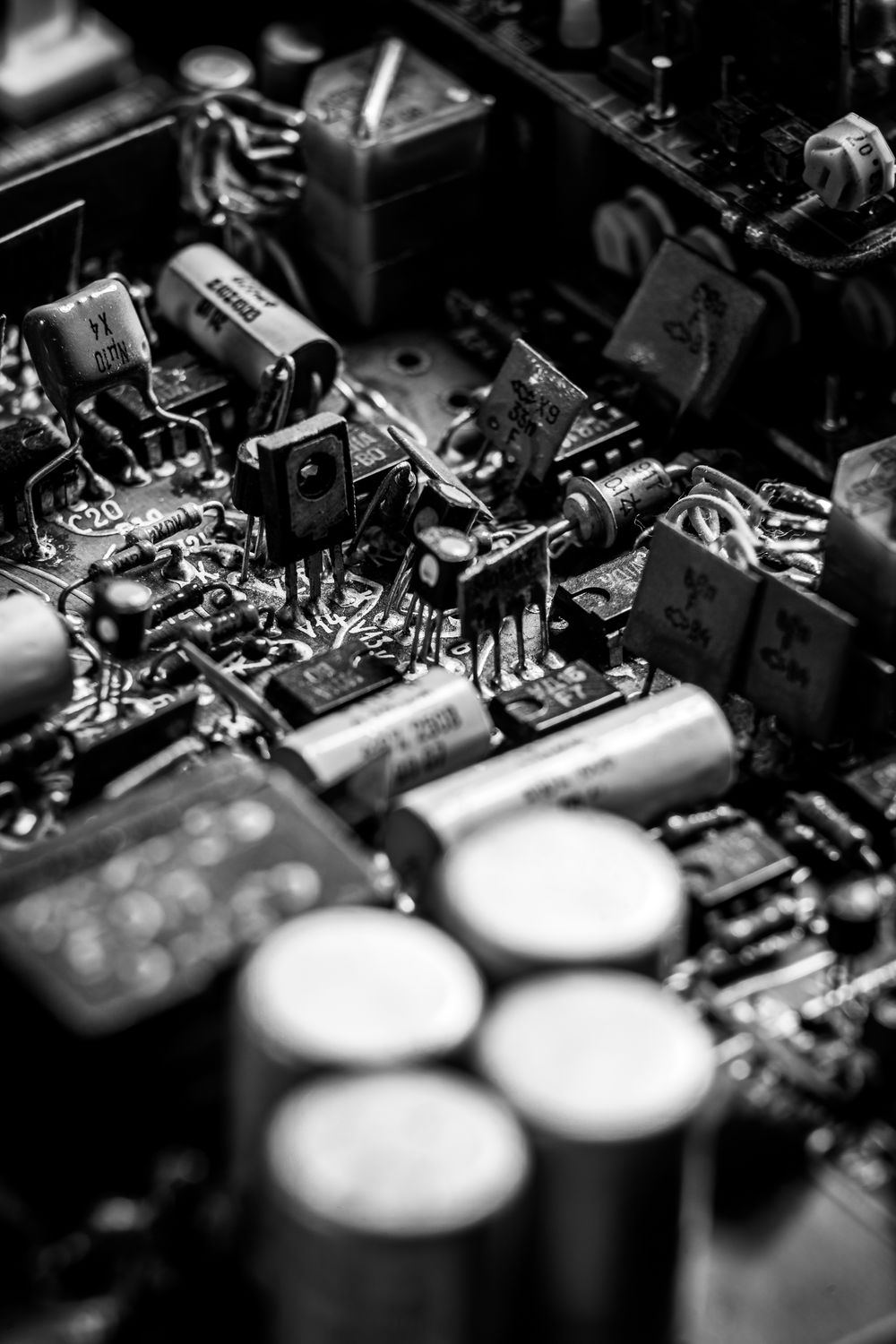
So uniformity across the load is part of the measurement. The chamber holds its condition even across every position a board can sit, proven by mapping the space, so a part at the edge of the load reaches the same life it would at the centre. A fatigue distribution is only honest if the one thing varying between samples is the solder, never the temperature they each saw.
Airflow does the evening out. A chamber for fatigue work moves its air briskly enough that every board in the load sees the same temperature as it ramps, no corner lagging the rest. The load is spaced so the air reaches each sample, fewer boards to a run buying a cleaner distribution, since a crowded chamber that shadows its samples reads a scatter the solder never had.
The board is half the test
A solder joint never fails alone; it fails as part of an assembly. The board carries half the mismatch that strains the joint, so its material and its thickness both shape the life the test measures. IPC-9701 fixes a standard board thickness, around 2.35 millimetres, so a result reflects the joint, free of an odd board’s influence.
So the test vehicle is specified, never improvised. The same component soldered to a thicker or a thinner board would crack at a different cycle, so the standard pins the board down along with the cycle, making the joint the one thing under study. A fatigue life means a particular part on a particular board, the pair tested as one.
The mounting matters alongside the board. How a part is attached, from the pad design to the solder volume laid by the stencil, feeds into the joint that gets tested, so a result reflects the assembly process and the part together. Two labs soldering the same component can read different lives if their assembly differs, which is why the standard controls the build with the same care it gives the cycle.
What a failed joint looks like
The crack tends to start where the strain piles up. In a leadless part the joint is loaded hardest at its outer edge, so a crack often begins at the heel or the corner of the solder and works inward along the line where the part meets the board. The path it takes depends on the joint’s shape and the solder’s grain, the failure finding the weakest line through the metal.
A cross-section tells the story after the fact. Cutting a failed joint open shows the crack’s path, how far it ran, where it started, which confirms the daisy chain’s electrical failure was a real fatigue crack, the kind the test set out to find. The chamber produces the failure; the microscope reads how it happened, the two together turning a cycle count into an understood one.
What can spoil a result
A fatigue life is easy to spoil without noticing. A chamber that overshoots its extreme on the way to dwell ages the joints harder than the count admits; a gap in the monitoring lets a joint fail between scans, logged a few cycles late; a board loaded where the air runs slack cycles cooler than its neighbours. None of these stops the test, so each can pass quietly into a result that looks clean.
Which is why the chamber is verified before it is trusted. The profile is checked against a reference and the uniformity mapped across the load, the monitoring proven to catch a fast failure, all before a long run begins. A fatigue life carries the weight of a measurement, so the instrument that produces it is held to a measurement’s standard, its cycle and its evenness documented alongside the count it returns.
From test cycles to field years
A test counts cycles in weeks; a product lives its cycles over years. The lab cycles fast and hard to fail the joints in a reasonable time, so the raw count of test cycles is not the field life directly. A model bridges the two, scaling the harsh test cycles into the milder, slower cycles a product sees in service.
That scaling rests on the physics of fatigue. An acceleration model relates the life under one cycle to the life under another by how far each swings and how the solder creeps, so a few thousand harsh test cycles can stand for many years of gentle field ones. The chamber delivers the harsh, countable cycles; the model carries the count out to the years the part will really last.
How long a life takes to measure
Measuring a fatigue life takes real time. A single cycle, with its two dwells and its two ramps, runs the better part of an hour, so a test aiming at thousands of cycles fills weeks, sometimes months, of chamber time. The joints have to be cycled until enough of them crack to draw a distribution; the tougher the solder, the longer the wait.
That cost is why the test cycles harder than the field ever will. A lab cannot wait the decade a product might last, so it picks a range and a pace that fail the joints in a workable time, then leans on the acceleration model to carry the fast result back to the slow reality. The chamber’s job is to run that long, hard schedule without a stumble, since a single excursion off the profile, days into a run, can spoil the life it was measuring.
What an honest IPC-9701 chamber provides
Everything an IPC-9701 chamber needs follows from the kind of answer it has to produce: a fatigue life that another lab could reproduce and a model could trust. That asks for more than the power to reach a temperature. It asks for precision and evenness, the patience to run thousands of cycles, with a way to watch the joints crack as they go.
It has to hold the exact cycle. The cycle’s extremes and its dwell and ramp all sit inside the narrow window the standard names, so the life the chamber measures is the life the standard defines, comparable to any other lab’s. A drift in any of them is a drift in the answer, so the chamber’s accuracy is the result’s accuracy.
It has to treat every sample alike. The condition holds even across the whole load, proven by mapping, so a clean distribution comes back, its scatter belonging to the solder alone, free of the box. A fatigue curve is only as trustworthy as the sameness of the samples behind it.
It has to watch the joints continuously. The daisy chains are monitored through every cycle, the resistance logged, the failures timestamped to the cycle, so no crack passes unseen between checks. A life test that only looked at the end would know which joints failed, never when, the one thing it set out to learn.
Together these make a chamber built to measure. It runs the standard’s cycle exactly and holds it even across every sample, watching each joint to the cycle it cracks, then handing back a fatigue life a model can carry into the field. That is the demand IPC-9701 places on the box: reproduce the cycle so faithfully that the number coming out means the same in every lab that reads it, a count of cycles earned the same way everywhere.
Common questions
What does IPC-9701 test?
IPC-9701 tests the thermal fatigue life of the solder joints that hold a surface-mount component onto its board. It thermally cycles a board warm and cold, again and again, while monitoring the joints, then counts the cycles each one lasts before it cracks. The result is a fatigue life in cycles. The standard measures how long the joints last, ending in a count of cycles, the life of the joint.
Why do solder joints crack under thermal cycling?
A component and its board expand by different amounts as the temperature changes, so the solder joint between them is sheared a little with every cycle. One cycle does no harm. Thousands work the solder back and forth until a fatigue crack starts at the worst-strained edge and grows across the joint. The long, hot dwell lets the solder creep, ageing the joint faster.
How does the test know when a joint cracks?
The parts are daisy-chain coupons, their joints wired in a continuous loop whose resistance is monitored through every cycle. A crack raises the resistance of its chain, and the standard counts a joint failed at the first time the reading sits twenty percent above its start across five or more consecutive scans. That turns a gradual crack into a definite cycle number.
What is the output of an IPC-9701 test?
The output is a fatigue life, usually a Weibull characteristic life, the cycle by which about sixty-three percent of a sample has failed. Many parts are cycled together because solder fatigue scatters, and their lives form a distribution, read together as one curve. That characteristic life is then scaled by an acceleration model into the years a product would last in real service.
Why must the chamber hold the cycle so precisely?
Because the fatigue life depends on the cycle that produced it. The same joint cracks at a different count under a wider range, a deeper cold, or a longer dwell, so a chamber that drifts off the standard’s profile reports a life that belongs to its own error. Only a chamber holding the exact extremes, dwell, and ramp gives a result another lab can reproduce and trust.
Part of the Envsin guide to semiconductor reliability testing. IPC-9701 measures the fatigue life of board-level solder joints, cycling them to failure and counting, so the chamber’s precision in reproducing the standard’s cycle is what makes the life it reports mean the same everywhere.