Dry Heat Test Chamber Configuration Per IEC 60068 2 2
IEC 60068-2-2 is the international standard for dry heat testing. A product goes up to a high temperature, holds there for a set time, and comes back. The chamber has a few jobs: reach one of the listed temperatures, hold the entire working space inside a narrow tolerance band for the full soak, keep the air dry, and guard against overheating.
A dry heat test asks one question: does the product still work and stay undamaged after time at high temperature. The standard makes every laboratory ask it the same way. A part qualified at one hundred and twenty-five degrees in one country matches a part qualified there in another. The standard fixes the temperatures a test may use, the tolerance the chamber must hold, the way the specimen is heated and powered, and the record. A chamber is judged on how well it meets those points under a real load.
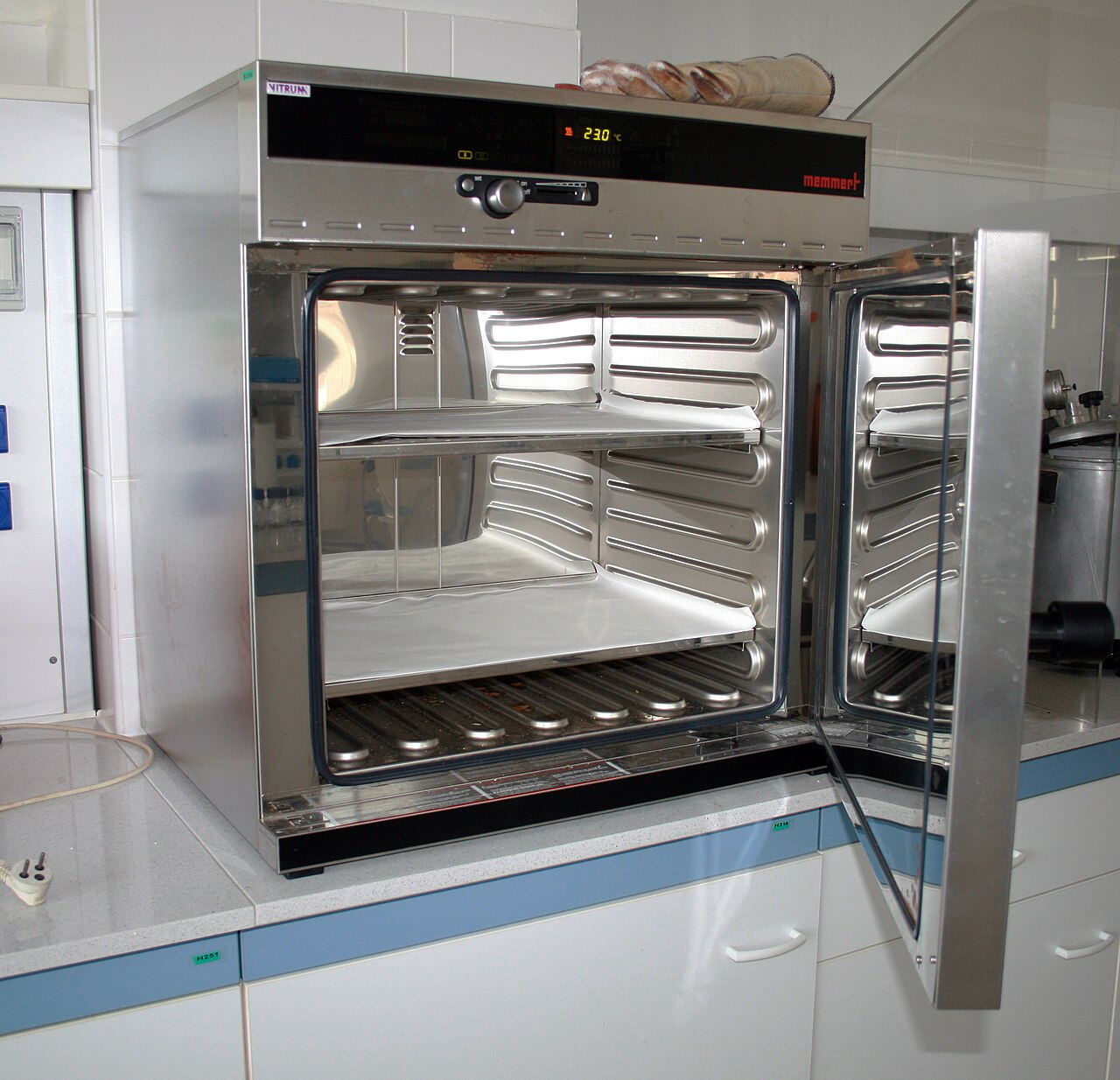
◆The list of preferred temperatures
The standard sets a list of preferred high temperatures. Laboratories test to the same numbers. The list includes thirty degrees Celsius, forty, fifty-five, seventy, eighty-five, one hundred, one hundred and twenty-five, one hundred and fifty-five, one hundred and seventy-five, and two hundred. The list reaches higher for high-temperature work. A test plan picks one of these. The reason is comparability. Accredited laboratories quote and certify against the published values. The mild values near seventy and eighty-five cover stored and operating electronics. One hundred and twenty-five is a common automotive and industrial point. The values above one hundred and fifty-five reach into aerospace and high-temperature plant.
The time matters. So does the temperature. The standard sets preferred soak times of 2, 16, 72, and 96 hours. The count starts when the specimen reaches temperature. A severity is always a pair: the temperature and the time.
◆What dry means for the chamber
One word in the name sets this test apart from damp heat. A dry heat chamber controls the temperature. It does not control the humidity. The physics of warm air does the rest. Relative humidity is the water vapour present divided by the maximum the air could hold at that temperature. The amount the air can hold rises steeply as it warms. A sealed parcel of room air, heated with no water added, falls to a few percent relative humidity. A chamber at one hundred degrees with no added moisture sits in single-digit humidity. The test stresses the specimen with heat alone.
This is the line between Test B and the damp heat methods. A dry heat chamber needs no humidifier, no water supply, and no wet-bulb sensor. It needs air handling that keeps outside moisture out during the soak. An unsealed box breathing room air gives a changing humidity the method does not intend. The dryness comes from heating sealed air and keeping the space closed.
◆What the two-degree tolerance means
The tolerance is a band of about two degrees around the target. The tolerance band has three parts. All three hold at once.
The first part is space. The band applies at every point a specimen can sit in the working space. The corners count. A reading at the control sensor alone does not satisfy it. At high temperature this is hard in practice. The walls and heaters radiate. Hot air rises and pools near the top. A loaded chamber sets up gradients a survey has to find.
The second part is time. The tolerance band holds for every minute of a soak that may run sixteen, seventy-two, or ninety-six hours. A heater cycling against an aging seal, a door opened to add a probe, a control loop hunting on a hot day: the record shows each one.
The third part is measurement. Two degrees means something only against instruments whose error is known. A sensor uncertain by half a degree leaves a degree and a half of real margin. An uncalibrated reading inside the tolerance band proves nothing. Large chambers get a wider band when their size makes two degrees impractical. The wider band is an allowance for size. Holding two degrees at the top of the range is the real work of a high-temperature chamber.
◆Choosing the severity
Each severity targets a different stress. A higher temperature brings out different mechanisms. Below about eighty-five degrees the test mostly probes function and drift, the way a part performs when warm. The softening of a plastic, the limits of a lubricant, and the offset of a clock crystal show in this range. Higher up, the chemistry of aging speeds up. The test begins to consume service life. A common rule of thumb puts the rate of many thermal reactions at roughly double for every ten degrees of rise. A soak at one hundred and twenty-five reaches an endpoint in far fewer hours. This is the basis of accelerated aging. The multiplier is an estimate for planning. The standard certifies no fixed value.
The soak is not idle time. A product held at a high temperature for hours reveals faults that a brief touch of heat hides. A solder joint near its melting point creeps. A plastic part near its softening point sags under its own weight. A lubricant thins and migrates. A semiconductor junction drifts. Some of these need hours at temperature to show. The preferred soak times of two, sixteen, seventy-two, and ninety-six hours give the slow faults time to appear. A two-hour soak proves the product works hot. A ninety-six-hour soak proves it endures. The severity in the plan picks the dwell the product’s service asks for. A longer dwell finds more, at the cost of chamber time.
◆The three test variants
The standard offers several ways to run the test. The recent editions keep three, all reaching temperature by a gradual change. Test Bb is for a specimen that gives off no heat of its own. Test Bd is for a heat-dissipating specimen brought to temperature unpowered. Test Be is for a heat-dissipating specimen left powered through the soak. The chamber holds the tolerance band around a part making its own heat. The older sudden-change variants, where a specimen was moved straight into a pre-heated chamber, have been removed. A test that needs an abrupt step belongs to the change-of-temperature methods.
◆The rate of change
The retained variants change temperature gradually. The rate is part of the method. A common average is near one degree per minute. The specimen then heats as one body, with no hot skin forming over a cooler core. A rise the core cannot follow builds internal stress that belongs to thermal shock and change-of-temperature methods. Holding the rate also keeps results comparable between laboratories whose heaters drive up at different speeds. The same rule governs the return at the end. The specimen comes back gradually. The cooling counts as part of the controlled exposure.
◆When the specimen has reached temperature
The soak is counted from the specimen. The preferred durations begin when the part has reached the test temperature. That moment comes after the controller’s display first reads the setpoint. Light specimens follow the air closely. A dense casting or a potted assembly lags the air by hours. Starting the clock at the display cuts the exposure the standard specifies. For heavy products a laboratory instruments the specimen itself, or an equal thermal dummy beside it, and starts the soak timer from that reading. An auditor reading the trace can see at once whether the soak was timed from the part or from the air.
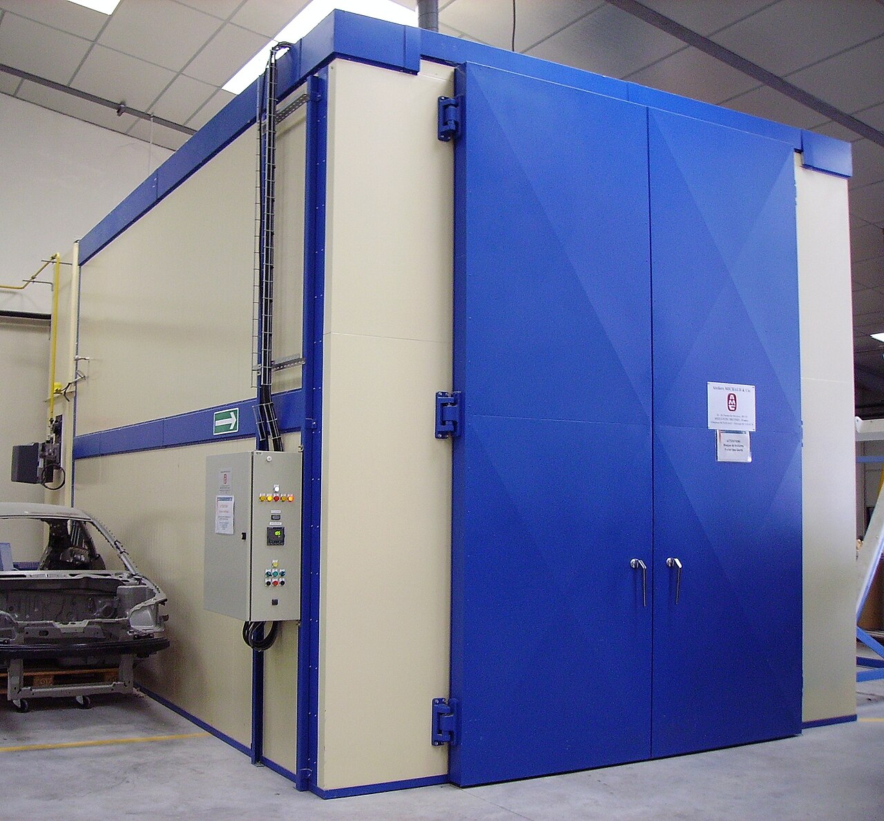
◆Holding the tolerance band across the hot space
Hot uniformity is the harder problem. Conditioned air leaves the heaters, moves through the workspace, and returns. Every specimen placed in that path changes it. Hot air rises to the top of a tall chamber. The floor stays cooler. The walls radiate onto whatever faces them. A densely packed load blocks circulation. It leaves a corner short of moving air. A forced-convection design, where a fan drives the air hard enough to even out the local differences, holds two degrees across a real load. Natural-convection ovens that drift several degrees top to bottom do not meet the same clause. The remedy is a mapping survey. Probes through the empty space and the loaded space find the warm and cool corners. The loading pattern then follows the mapped airflow.
An empty chamber is the easy case. The numbers on a datasheet often come from one. A loaded chamber is the real test. Every specimen in the working space blocks some airflow and adds some mass. A dense load slows the heat-up. A tall stack leaves the air at the top hotter than the air at the floor. A specimen pressed against a wall takes radiant heat the air-temperature sensor never sees. The tolerance a chamber holds empty is not the tolerance it holds full. The honest figure is the one measured with the real load aboard, in the real loading pattern. A mapping survey of the loaded space finds the warm corners the brochure never mentions.
◆When the test itself goes wrong
A dry heat test can fail in ways that have nothing to do with the product. A door opened to add a probe drops the temperature and restarts the climb. A control loop tuned for an empty chamber hunts when a load is added, swinging above and below the band. A heater element ages and loses power. The chamber that reached two hundred degrees last year tops out at one hundred and ninety this year. A draught from a failing door seal pulls heat from one corner. Each of these shows in the trace. A record read with care separates a product fault from a chamber fault. A unit that failed while the trace shows a clean, steady soak failed on its own. A unit that failed while the chamber swung out of band has a result no one can trust.
◆Powered specimens and self-heating
A specimen running under power in Test Be makes its own heat. The air moving past it sets how much of that heat the test carries away. A part that dissipates a few watts sits a little above the air around it. A part that dissipates a great deal can sit far above the chamber setpoint, its own surface well above the number on the controller. Brisk chamber airflow carries heat away from a running product and brings its surface back toward the air temperature. The product runs hotter in the still air of its real housing. A part with hot internals and a cooler case holds a steep gradient of its own. A probe on the case understates the junction within. The airflow has to do two things at once: hold the air at the setpoint, and let the specimen sit at the temperature its service would give. The load is arranged to represent the service case it will meet.
◆The independent over-temperature protector
A chamber that drives to two hundred degrees needs a second line that does not depend on the first. The control loop holds the setpoint. A separate over-temperature protector, with its own sensor and its own cutout, removes power from the heaters if the temperature climbs past a set limit. The fault that lets a chamber overheat is often a failure of the control sensor or the control loop. The protection cannot share either. A control thermocouple that comes loose reads low. The loop then calls for more heat. The true temperature climbs. Only a protector with an independent sensor catches it. At dry heat temperatures an unchecked climb risks a fire. Insulation, wiring, and a polymer specimen all give a runaway at two hundred degrees plenty to ignite. The protector belongs in the configuration of every high-temperature chamber. Its limit is set above the test temperature and below the danger point. It is verified to trip as part of commissioning and on a schedule after.
◆What each rung costs the machine
Up to about one hundred and fifty-five degrees, an ordinary forced-convection oven carries the load with familiar engineering: resistance heaters, mineral-wool insulation, and seals and wiring of common materials. The frequent points at seventy and one hundred and twenty-five sit inside this range. General-purpose chambers cluster there. The steps to one hundred and seventy-five and two hundred cross into high-temperature construction. Door gaskets have to survive the heat. Insulation has to be thick enough to keep the outer skin safe to touch. Wiring has to be rated for the inner temperature. Fans and bearings have to run hot. A machine specified to two hundred is a heavier build.
Reaching two hundred degrees and holding two degrees at two hundred under load are separate abilities. Heater power sets the temperature a chamber reaches. Holding the tolerance band there takes power, airflow, and control together. A machine whose maximum is exactly the test temperature runs the soak at full effort, with nothing in reserve for an aging element or a hot room. Read a datasheet for the figure the standard limits. The clause is about holding, shown in the uniformity and fluctuation figures, stated at the temperature you will sell, under a declared load.
◆Sensor placement and the record
The control sensor runs the loop, set at the point the manufacturer tuned around. The proof of the test comes from separate monitoring probes. They sit at the specimen’s position, calibrated against references with current certificates. The rule is to record at the specimen’s representative point, and at the spots a mapping survey has shown to run to the extremes. A single centre probe covers only the centre. The corners need their own probes, or the spatial part of the tolerance stays unproven. The instrumentation belongs on the original order.
The file is what turns hours of heat into a qualification. It holds the trace of the monitored points through the rise, the soak, and the return, the calibration certificates, the photograph of the load, the verification of the over-temperature protector, and the deviations with their dispositions, signed by someone accountable. A reading per channel per minute through the soak, taken more often during the rise, keeps the file small enough to store. The detail still answers later questions. The file outlasts the run. Years later, the people who ran the test have moved on. The record is the only account of what the product saw. A laboratory that builds the file as the test runs passes an audit with little effort.
A reading at two hundred degrees means nothing without a calibrated sensor behind it. The monitoring probes that prove the test are calibrated against references with current certificates. The references trace to a national standard, checked on a fixed cycle. A probe drifts with age and with the heat it has seen. A thermocouple cooked at two hundred degrees for thousands of hours is not the thermocouple it was. The calibration interval catches that drift before it corrupts a record. An out-of-date certificate puts every reading taken under it in doubt. A laboratory that lets its calibration lapse can hold the band perfectly. It still fails an audit, because no one can prove the band was where it says.
◆From the procedure to the report
A dry heat test runs to a written procedure, set down before the run. The procedure names the temperature, the soak, the variant, and the rate. It names where the monitoring probes sit. It names the recovery before the final measurement. The laboratory follows it step by step: bring the chamber to temperature, prove the specimen has arrived, hold the dwell, return at the controlled rate, recover, measure. Each step leaves a mark in the record. The report at the end is not a single pass or fail. It is the trace, the calibration certificates, the load photograph, the protector check, and the deviations with their dispositions. A reader years later can see exactly what the product saw, and trust that it saw it.
◆Where dry heat sits in the test family
Dry heat is one test in a large family. IEC 60068 covers the environmental tests a product meets. Test A is cold. Test B is dry heat. Other parts cover damp heat, where the air is held humid, and the change-of-temperature methods, where the temperature is moved fast on purpose. A product’s qualification plan names the tests it has to pass. Dry heat answers one question among many: does the product survive and work after time at a high, steady temperature. It says nothing about humidity, about cold, or about thermal shock. Those are other tests, run on their own. A part qualified to Test B has shown one thing well. The plan picks the tests the product’s service demands. Dry heat earns its place when the service runs hot.
◆Questions on dry heat testing to IEC 60068-2-2
What temperatures does IEC 60068-2-2 use?
The preferred high temperatures begin at plus thirty degrees Celsius and include forty, fifty-five, seventy, eighty-five, one hundred, one hundred and twenty-five, one hundred and fifty-five, one hundred and seventy-five, and two hundred. The list reaches higher for high-temperature work. They pair with soak times of 2, 16, 72, or 96 hours, counted from specimen stability. A specification chooses the pair. The laboratory reaches the value, proves the specimen has arrived, and holds the tolerance band for the stated hours.
Why is the humidity not controlled in a dry heat test?
Because the method tests a product with heat alone. Relative humidity is the water present divided by the maximum the air could hold. The amount it can hold rises steeply as the air warms. Heating a sealed parcel of air with no water added drops its humidity toward a few percent on its own. A dry heat chamber needs no humidifier and no water supply. It keeps the space closed against outside moisture during the soak. Holding humidity high on purpose is a separate family of damp heat methods.
What is the difference between variants Bb, Bd, and Be?
They differ in what the specimen contributes to the heat. Bb is for a part that gives off no heat of its own. Bd is for a heat-dissipating part brought to temperature unpowered. Be is for a heat-dissipating part left powered through the soak. The chamber holds the tolerance band around a specimen that is making its own heat. All three reach temperature gradually. The older sudden-change variants have been removed. An abrupt step belongs to the change-of-temperature methods.
How tight is the temperature tolerance?
The working tolerance is about two degrees around the target, applied across the full working space for the full soak and judged on calibrated instruments. Large chambers get a wider allowance where their size makes two degrees impractical. The strictness is in the reach. The corners count. The cycling of the heaters counts. An uncalibrated reading does not. Holding two degrees at the top of the range is the real work of a high-temperature chamber.
Why does a dry heat chamber need an independent over-temperature protector?
Because the fault that lets a chamber overheat is often a failure of the control sensor or loop, the protection cannot share either. A separate protector, with its own sensor and cutout, removes power from the heaters if the temperature passes a set limit. It overrides a control loop calling for more heat. At dry heat temperatures an unchecked climb risks a fire. That is why the protector is part of the configuration and is verified to trip on its own evidence.
How long is a dry heat soak?
The standard sets preferred soak times of two, sixteen, seventy-two, and ninety-six hours. The plan picks one to match the product and the question. A short soak proves the product works while hot. A long soak proves it endures hours at temperature, where slow faults like creep and migration appear. The clock starts when the specimen reaches the test temperature. It does not start at the air display. A heavy part lags the air. Its soak starts later than a light one’s.
Why does reaching two hundred degrees not mean holding it?
Heater power decides the temperature a chamber can reach. Holding two degrees there takes power, airflow, and control working together. A machine whose maximum is exactly the test temperature runs the soak at full effort, with nothing in reserve for an aging element or a warm room. The figure that matters on a datasheet is not the maximum. It is the uniformity and the fluctuation, stated at the temperature you will use, under a declared load. A chamber bought on its top number can reach the rung. It can still drift out of band while it holds it.
Does an empty chamber hold the same band as a loaded one?
No. An empty chamber is the easy case. Datasheet numbers often come from one. A load blocks airflow, adds mass, and sets up gradients an empty chamber never shows. A tall stack runs hotter at the top. A specimen against a wall takes radiant heat the air sensor never reads. The honest tolerance is the one measured with the real load aboard, in the real loading pattern. A mapping survey of the loaded space finds the warm corners. The loading pattern is set to keep every specimen inside the band.
How does dry heat differ from damp heat and thermal shock?
Dry heat holds a high, steady temperature and lets the humidity fall as the air warms. Damp heat holds the humidity high on purpose, to find the faults moisture brings. Thermal shock moves the temperature fast between a hot and a cold point, to stress a part with the speed of the change. Each is a separate test, in a separate part of the standard. A product’s plan runs the ones its service demands. Dry heat answers for time at a high temperature, and nothing else.
Why is the cooling rate controlled at the end too?
The same gradual rate that governs the climb governs the return. A specimen pulled from two hundred degrees into room air would meet a thermal shock the dry heat method never intended. The controlled return brings the specimen down as one body, with no cold skin forming over a hot core. The cooling counts as part of the controlled exposure, in the record like the rest. The recovery period follows, before the final measurement. The product returns to room conditions before anyone reads it.
Envsin builds dry heat test chambers that hold the IEC 60068-2-2 band from the lowest value to a two-hundred-degree maximum, with the airflow, the safety, and the record the standard asks for.