A guided tour of every part inside a modern office copier
Open the front cover of a Canon iR-ADV C3826i, a Ricoh IM C3000, or a Konica Minolta bizhub C360i and the same set of components stares back. Same paper trays. Same imaging unit stack. Same fuser. Same controller board. Same finishing add ons. The chassis brand and color differ. The internal architecture has been standardized across the industry over thirty years of convergent engineering.
Walk the chassis from top to bottom and the entire machine fits in roughly fifteen named components. Knowing them by name turns service tickets and dealer conversations into different conversations entirely.
Top of the chassis. The platen and document feeder
The flat glass surface at the very top of the machine is the platen, sometimes called the original glass. Place a single page face down on the platen, close the cover, and the scanner reads the page from underneath. The platen on most office MFPs is sized for A3 paper, 297 by 420 millimeters, even on machines that print mostly A4. The A3 platen lets the machine handle a folded magazine, an oversized contract, or two A4 pages side by side without cutting them.
Above the platen sits the automatic document feeder, the ADF. The ADF is a hinged unit that holds a stack of original pages and pulls them through a separate scan path one at a time. Standard ADF capacity ranges from 35 to 200 sheets depending on segment. The mechanism inside the ADF includes a pickup roller that takes the top sheet off the stack, a separation pad that prevents two sheets from feeding at once, a transport drum that moves the sheet across the scan glass, and an output tray that catches the scanned page on the way out.
 Higher segment ADFs use a single pass duplex design, where two scan heads read both sides of a page in one feed pass. Lower segment ADFs use reverse ADF, where the page feeds through, gets reversed, and feeds through a second time to scan the back. The everyday distinction between feeder types and where they show up in different segments is unpacked at What the industry copier segments from one through six actually mean for you.
Under the platen. The scanner unit
Below the platen sits the scanner assembly. The active component on most modern MFPs is a contact image sensor, abbreviated CIS, which spans the full width of the platen and reads a single line of pixels at a time. As the CIS bar moves under the platen, it captures the page line by line. The CIS lights itself with rows of red, green, and blue LEDs that illuminate the original. Reflected light hits the sensor strip directly, no mirrors involved.
Older machines, including production class units that need higher color depth, use a charge coupled device sensor, abbreviated CCD. The CCD sits at the bottom of the chassis and receives light from the platen via a moving lamp and a series of mirrors that fold the optical path so the lamp can travel under the platen while the sensor stays put. CCD scanners produce slightly better color reproduction at higher resolutions but cost more and require precise mechanical alignment of the mirror array.
 The scan resolution on the platen reaches 600 dots per inch on most office MFPs, with 1200 dpi available on higher segment units for archival scanning of detailed originals. Through the ADF, scan resolution is the same but throughput is higher because the ADF handles continuous feeding rather than the platen's one page at a time. The full mechanical sequence that turns a piece of paper into either a copy or a digital file is at How a photocopier actually works in six clear steps.
Middle of the chassis. The imaging unit stack
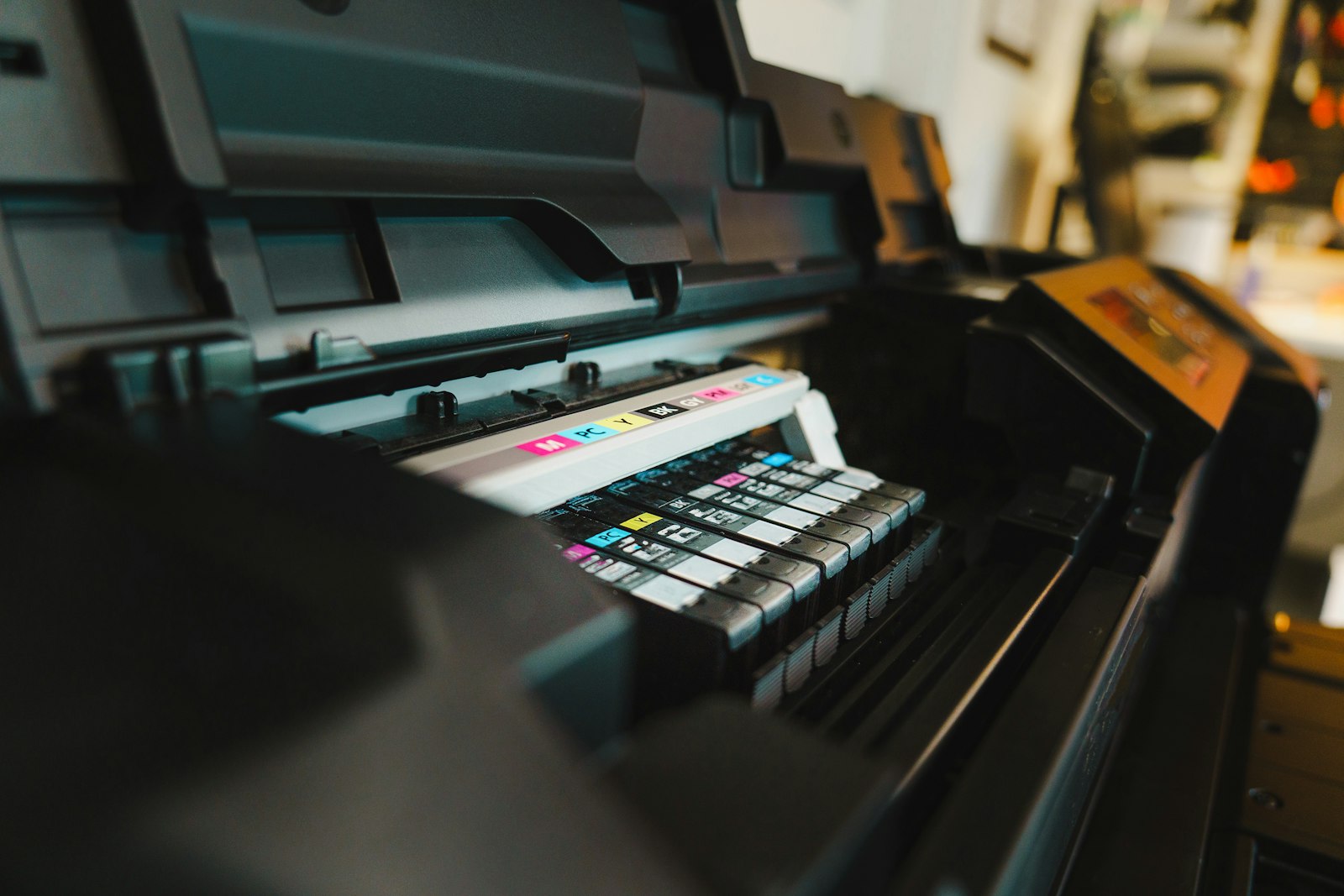
The center of the machine, behind the front cover, holds the imaging units. A monochrome MFP carries one imaging unit. A color MFP carries four, stacked vertically, one each for cyan, magenta, yellow, and black. Each imaging unit is a self contained module containing a photoreceptor drum, a charge roller, a developer unit, and toner supply. Pull the front cover open, lift the small lever, and the imaging unit slides out for replacement.
The drum sits at the center of each imaging unit. A polished aluminum cylinder coated with an organic photoconductor film, typically based on phthalocyanine pigments. The drum carries a uniform negative charge from the charge roller and accepts the latent image from the laser exposure unit. Drum diameters range from 30 to 60 millimeters depending on machine class, with larger drums on higher speed units to spread wear over more surface per page. Drum life on most office class machines runs between 75,000 and 200,000 pages. Kyocera drums are rated to last the full life of the machine, an engineering trade off that lowers per page cost while raising hardware cost.
Adjacent to each drum sits the developer unit. Inside the developer unit, magnetic carrier beads coated with toner particles rotate past a magnetic roller. The roller presents a thin brush of toner to the drum. Where the drum carries a low charge from laser exposure, toner jumps onto the drum. Where the drum carries full charge, toner stays on the carrier beads. Developer life runs to roughly 200,000 pages before the carrier beads degrade and need replacing, although many machines use disposable developer integrated with the drum unit so the entire imaging unit replaces together.
Behind the imaging units. The laser scanning unit
 The laser scanning unit, abbreviated LSU, sits behind or above the imaging unit stack. The LSU contains a laser diode, a rotating polygonal mirror with six or eight reflective facets, and a series of focusing lenses arranged in a sealed optical path. The diode pulses thousands of times per second. The polygon mirror rotates at 20,000 to 40,000 revolutions per minute, painting the laser pulses into horizontal lines across the drum surface.
Each color station in a color machine has its own LSU, or in some lower cost designs, one LSU with multiple beam outputs feeding all four imaging units. The LSU is sealed at the factory and carries no user serviceable parts. Failures in the LSU are uncommon but expensive when they happen. Replacement runs to several hundred euros and requires a service technician.
OKI uses LED arrays in place of laser scanning units across most of its lineup. An LED array eliminates the polygon mirror and consists of a fixed line of LEDs corresponding to each pixel position across the drum width. LED units have fewer moving parts but cost more in component count. The trade off shows up at the spec sheet level only on machines from manufacturers that use one design across the entire range.
Below the imaging units. The transfer belt and secondary transfer
The vertical belt that runs past the four color imaging units is the intermediate transfer belt, abbreviated ITB. It catches the toner image from each imaging unit in sequence as it rotates past, layering CMYK on its surface. The belt material is polyimide or PVDF, around 60 to 100 micrometers thick, mounted on rollers that maintain tension and tracking. Belt life on office class machines ranges from 200,000 to 600,000 pages. Higher segment units run heavier belts rated for longer life.
 Below the belt sits the secondary transfer roller. Paper enters from the side, passes between the belt and the transfer roller, and the toner image jumps from the belt onto the paper under the influence of a positive voltage applied to the secondary transfer roller. After the secondary transfer, the paper continues into the fuser carrying all four colors at once, while the belt continues rotating to be cleaned by a separate cleaning blade and prepared for the next page.
The secondary transfer roller and the belt cleaner are both wear parts. Belt cleaning blades typically last 100,000 to 250,000 pages and are replaced as part of a maintenance kit on most machines. The full sequence of how the four color separations register and combine on the belt is at How a color copier turns one image into four layers of toner.
The back end of the paper path. The fuser
After the secondary transfer, paper enters the fuser unit. The fuser consists of two pressure rollers running at temperatures between 175 and 200 degrees Celsius. The upper roller is heated, often by an internal halogen lamp or by an induction coil wrapped around a steel cylinder. The lower roller is silicone rubber on a steel core. The two rollers press together with several hundred kilograms of force across their length, creating a narrow nip through which paper passes in 10 to 30 milliseconds.
The fuser is the highest power consumer in the chassis. Heating elements draw 800 to 1,500 watts during warm up. The fuser is also the most common failure point on heavily used machines. Heating element burnouts. Pressure roller flat spots from sitting hot for long periods. Surface wear on the upper roller's PFA coating. Most maintenance kits sold by manufacturers center on fuser replacement at intervals of 200,000 to 500,000 pages.
Modern induction heating fusers are faster to warm up than older halogen designs, reaching operating temperature in 5 to 15 seconds from sleep instead of 30 to 60 seconds from a cold start. The faster warm up allows machines to drop into deeper sleep modes without making users wait for first copy. The first copy out time number on the spec sheet is largely a function of fuser warm up speed.
Bottom of the chassis. Paper trays and the pickup system
The bottom half of the chassis is mostly paper handling. Office MFPs ship with two to four paper trays standard, each holding 250 to 1,000 sheets, with optional add on trays bringing total capacity to 5,000 sheets or more. A bypass tray on the side of the machine handles envelopes, labels, transparencies, and small one off jobs without interrupting the normal trays.
Each tray has a pickup roller that takes the top sheet off the stack, a separation pad or roller that prevents double feeds, and a feed roller that pushes the sheet into the registration roller assembly. The registration roller assembly aligns the leading edge of the paper to the imaging unit timing, ensuring the toner image lands on the page in the right position. Misalignment at the registration roller produces skewed output. Most paper jam errors that show as J1 or J2 codes on the panel originate at the registration roller assembly or the tray pickup rollers.
 Pickup rollers wear with use, particularly with low quality paper or recycled paper that sheds dust. A worn pickup roller fails to grip paper consistently and produces frequent jam errors. Roller replacement is one of the most common service interventions on heavily used MFPs and is included in standard maintenance kits.
The brain. Controller board and electronics
Tucked into the back of the chassis, behind a sheet metal panel, sits the controller board. An embedded computer running custom Linux on most major brands. The controller manages the touchscreen panel, the print queue, the scan workflows, the address book, the user authentication system, the cloud connectors, and the SNMP and IPP interfaces that allow IT teams to monitor the machine from the network. The board hosts the print rasterizer that converts incoming PCL or PostScript jobs into the bitmap format that drives the laser scanning unit.
A hard drive or solid state drive sits attached to the controller. Capacity ranges from 320 GB on entry units to 1 TB on higher segment models. The drive caches recent jobs, holds the address book, stores held print jobs released by PIN, and on machines configured for it, archives every print job for audit purposes. Modern drives are encrypted at AES 256, and the controller runs a scheduled overwrite routine on deleted data. Both features become important when the machine reaches end of lease and needs to be decommissioned.
The controller board carries the ports on the back of the chassis. Gigabit Ethernet. USB host ports for direct printing from drives. A serial port for legacy diagnostics. A phone line jack on machines with the fax module installed. Wi Fi and Bluetooth on machines that support wireless. The everyday distinction between this controller assembly and what a desktop printer carries instead is laid out at How a photocopier differs from a printer an MFP and a copier in everyday office life.
Outside the core chassis. Finishing assemblies
Optional finishing units bolt onto the side or back of the machine. The most common is a stapler finisher, which collects pages output from the chassis and staples them into sets of up to 50 sheets. Higher segment finishers extend to 100 sheet stapling, multi position hole punching, and saddle stitch booklet making for runs up to 50 sheets. Production class equipment adds perfect bind, square fold trim, and three knife trim modules.
Finishers are physically separate units with their own paper paths, sensors, and motors. They communicate with the main chassis controller over a dedicated bus. Failures in the finisher rarely affect the main chassis. A jammed stapler can be cleared without interrupting print operations on the rest of the machine. Higher segment finishers run their own onboard processors to manage the complexity of multi station finishing.
Add on accessories also include large capacity paper trays, fax modules, hard drive expansion modules, integrated card readers for user authentication, and on some manufacturers, banner sheet kits for handling oversize media. Each accessory adds to the chassis size and to the lease cost. Most Spanish SMB offices add a basic stapler finisher and skip the rest. Where the dividing line falls between a typical office configuration and a more elaborate one tracks segment classification more than finishing capability per se.
Fifteen named components. Platen, ADF, scanner, imaging units, drums, charge rollers, developer units, laser scanning unit, transfer belt, secondary transfer, fuser, paper trays, pickup rollers, controller, finisher. Knowing the names by sight and by function makes service conversations faster, dealer proposals clearer, and operating costs more predictable.