Cold Test Chamber Temperature Range And Tolerance Per IEC 60068 2 1
IEC 60068-2-1 is the international standard for cold testing. A product goes down to a low temperature, stays there for a set time, and comes back. The chamber has two jobs: reach one of the listed temperatures, and hold the entire working space inside a narrow tolerance band for the full soak.
A cold test asks one question: does the product still work and stay undamaged after time at low temperature. The standard makes every laboratory ask that question the same way. A part qualified at minus forty in one country matches a part qualified at minus forty in another. To do that, the standard fixes four things: the temperatures a test may use, the tolerance the chamber must hold, the cooling rate, and the record. A chamber is judged on how well it meets those points under a real load.
◆What the cold does to a product
Cold breaks and stalls a product in ways heat does not. A plastic that flexes at room temperature turns brittle and cracks. A seal stiffens and lets a leak past. A grease thickens until a mechanism stalls. A battery loses the chemistry that gives it current. A liquid-crystal display slows until it smears. A solder joint and the board it sits on shrink at different rates. The strain finds a weak joint. None of these need the cold to be extreme. Many show at minus forty, the common automotive floor. The test holds the product at the cold long enough for the slow ones to appear, then asks whether it still works and survived undamaged.
◆The list of preferred temperatures
The standard sets a list of preferred low temperatures. Laboratories test to the same numbers. The values run from minus sixty-five up to plus five degrees Celsius. The rungs are minus sixty-five, minus fifty-five, minus fifty, minus forty, minus thirty-three, minus twenty-five, minus twenty, minus ten, minus five, and plus five. A test plan picks one of these. The reason is comparability. Accredited laboratories quote and certify against the published values. A non-standard temperature needs a fresh justification every time. The bands map to service. The mild rungs near minus ten and minus twenty-five cover indoor and general outdoor use. Minus forty is the common automotive and industrial minimum. Minus fifty-five and minus sixty-five cover aerospace, defence, and high-altitude work. A product needs the rung its own service sees, plus a safety margin.
The time matters. So does the temperature. The standard sets preferred soak times of 2, 16, 72, and 96 hours. The count starts when the specimen reaches temperature. A severity is always a pair: the temperature and the time. A pair with one value missing leaves the exposure undefined.
◆What the two-degree tolerance means
The tolerance is a band of about two degrees around the target. Many laboratories miss it. The tolerance band has three parts. All three hold at the same time.
The first part is space. The tolerance band applies at every point a specimen can sit in the working space. The corners count. A reading at the control sensor alone does not satisfy it. A chamber can show minus forty at the sensor. A back corner can sit at minus thirty-six. That chamber is out of tolerance.
The second part is time. The tolerance band holds for the full soak. It holds through compressor cycles, through defrost, and through the small moves of the control loop. A machine that drops past the limit twice an hour spends its test moving in and out of compliance.
The third part is measurement. The result carries only the authority of its instruments. A sensor uncertain by half a degree leaves a degree and a half of real margin. An uncalibrated reading of minus forty proves nothing. Space, time, and measurement all have to hold. A miss on any one of the three makes the result only a number on a display. Large chambers get a wider band when their size makes two degrees impractical. The standard often allows three degrees down to a point and five degrees toward the coldest rungs. The wider band is an allowance for size. The principle does not change. Two figures describe the tolerance band in practice. Uniformity is the spread across the space at one moment. Fluctuation is the change at a single point as time passes. A datasheet should give both, at the rung and the load the test will use.
◆Choosing the severity
The temperature and the time come from the product specification. A component standard, a customer specification, or a climatic class names the severity. The laboratory reads that requirement first. It also checks the electrical state. The product is tested switched off, powered throughout, or powered only for checks at the end. The three cases stress different faults. An unpowered soak finds brittle materials and mechanical faults. A powered soak adds marginal electronics to the list. The powered cases carry one more choice. The product can run its real workload, or a standby load. An idle device draws little current and sits near the chamber air. Under full load it sits well above the air. The procedure should name the electrical state. Load can bring out a cold failure that idle testing misses.
Some specifications leave room. The honest choice is the rung the product’s service environment calls for, plus one step of margin. A cabin product tested to minus sixty-five proves conditions it will never meet, at real cost. An alpine sensor tested to only minus ten leaves out the cold of service. The severity in the report stands long after the meeting that set it. Settle it once, with the product’s service data on the table.
◆The rate of cooling
The standard limits how fast the chamber may change the air temperature. The usual figure is near one degree per minute. The limit protects the meaning of the test. This method checks how a product tolerates low temperature. Tolerance of fast change is a separate subject. That belongs to the thermal shock and change-of-temperature methods.
A controlled descent keeps the inside of the specimen close to the air. Plastics, potting compounds, and laminated assemblies follow the air slowly. A descent the core cannot follow builds internal stress. A cold shell forms around a still-warm centre.
The load changes the rate. Adding thirty kilograms of metal slows the descent. A test plan booked by the brochure rate finds the gap on the schedule. The right rate for a load comes from a measured pull-down with that load aboard. The empty-chamber figure on the brochure does not apply. The rate also has a floor. Too slow wastes chamber time and money. The controlled rate is a window. It runs fast enough to stay economical. It runs slow enough to keep the specimen together.
◆When the specimen has reached temperature
The soak clock starts when the specimen reaches temperature. Air settles in minutes. A dense assembly can lag the air by hours. Starting the count at the air display gives the product a shorter, easier test.
The standard treats arrival as stability. The specimen, or a point on it, settles inside the band and stays there. For a light part the lag is short. For anything heavy, the only honest clock is a probe on the specimen, or on a dummy of the same mass. Thermal mass sets the lag. The denser the part, the longer the wait. A sixteen-hour severity on a heavy specimen runs sixteen hours after arrival. Arrival alone can take half a shift. An auditor finds the gap by laying the specimen probe trace over the air trace.
The soak at the bottom is where the slow faults show. A short hold proves the product starts and runs in the cold. A long hold proves it endures hours in the cold with no slow fault creeping in. A grease that thickens, a seal that takes hours to stiffen through its bulk, a condensation path that builds with time: these need the dwell to appear. The preferred soak times of two, sixteen, seventy-two, and ninety-six hours give them the time. A dense product takes hours just to reach the cold at its core, before the dwell even starts. The clock starts from the part, once the part itself reaches the cold. The severity names the dwell the product’s service asks for. A longer dwell finds more, at the cost of hours in the chamber.
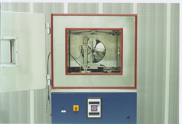
◆Holding the tolerance band across the space
Airflow and loading decide spatial uniformity. Conditioned air leaves the evaporator, sweeps the workspace, and returns. Every specimen in that path changes it. Loading a chamber that held one degree empty can push it past two degrees. The warmest point sits behind the largest box.
The pattern of failure is predictable. The corners furthest from the supply run warm. So does the shadow behind a bulky specimen. So does the layer nearest a door seal. The pattern repeats from machine to machine in a product family. An experienced operator can point to the likely warm corner of a chamber model they have not run before. Laboratories learn the map of their own chamber. They place specimens to suit the airflow. They keep the clearances the manual asks for. The other option is finding the warm corner during an audit.
A survey ties this to evidence. Calibrated probes map the empty space first, then the loaded space. The survey repeats on a set cycle. It runs again after any move or major repair. Between surveys, disciplined loading keeps the geometry true. A photograph of the load in every file makes the discipline checkable years later, for one press of a shutter per run. The fix for a warm corner is mechanical. A stronger fan evens the space. Baffles steer air past dead corners. Shelving keeps specimens out of the supply stream. None of it helps if the load blocks the return.
◆Holding the tolerance band across the hours
Over time, the machine’s own cycle is the disturbance. Compressors stage on and off. A hot-gas or electric defrost runs on a schedule. Each event moves the workspace temperature. A well-set chamber keeps the move inside a fraction of the band. Neglect turns each defrost into a brief temperature swing. The recorder writes it down in full. The fix is set at commissioning and upkeep. Control parameters are tuned to the load. Defrost is scheduled around the soak-critical windows. The move is worth watching in the trace. Drift here is an early sign of frost on the coil, or of a refrigeration unit losing headroom. A weekly read of the trace gives free maintenance warning, early enough to act on.
◆Powered specimens and the air around them
A powered specimen makes its own heat. The air moving past it sets how much of that heat the test carries away. Brisk chamber airflow strips warmth from a running product. The product runs hotter in the still air of its real installation. The chamber can then report a survival the product never had in service. The standard handles this in its method for heat-dissipating specimens. It keeps air movement around the product low. Surface temperatures then land near what free air would give.
The airflow has to do two things at once. It needs enough circulation to hold the space in tolerance. It needs slow air at the specimen to keep the result honest. Placement, baffles, and the chamber’s own air-speed setting all help. The report should state what the air was doing around a dissipating specimen. On a powered product, local airflow changes the result. A sealed cast housing barely feels the air around it. For an open frame with a hot internal part, the air is almost everything. Air speed at the specimen is measurable. A vane or hot-wire anemometer reads it. The number goes in the report. A powered result cannot be repeated without it.
A product that must work in the cold has to be tested working in the cold. An unpowered soak proves the materials survive. It says nothing about whether the device switches on at minus forty. A powered cold test answers that. The chamber holds the product at the low temperature. The product is switched on cold, the way a car left out overnight is started on a winter morning. A battery that holds charge in a warm room may not turn an engine when its chemistry has slowed in the cold. A clock crystal drifts. A capacitor’s value shifts. The cold start is its own test. The procedure names it when the product’s service includes it.
◆Frost on the dry side of the test
Every door opening brings in humid room air. Everything below freezing inside collects it as frost. On the cooling coil, frost insulates the refrigeration and erodes the band. On the specimen, it adds a layer of ice the test never specified. In the record, it shows up as a slow warm drift that looks like a refrigeration fault. The countermeasures are mostly procedural and cheap. Doors stay shut through the soak. Entries are batched and logged. A dry-air or nitrogen purge is justified on chambers that have to be opened mid-test. A two-minute door event at minus forty can cost twenty minutes of recovery.
Condensation matters chiefly at the end of the test. A cold specimen meets warm laboratory air. Water films across circuit boards and into connectors. This is the reason the recovery stage exists. A hurried unload lets corrosion begin from the surface water. The problem is worst in humid climates. A dehumidified recovery zone, or a dry cabinet for small specimens, removes the risk for the price of a bench.
◆What each rung costs the machine
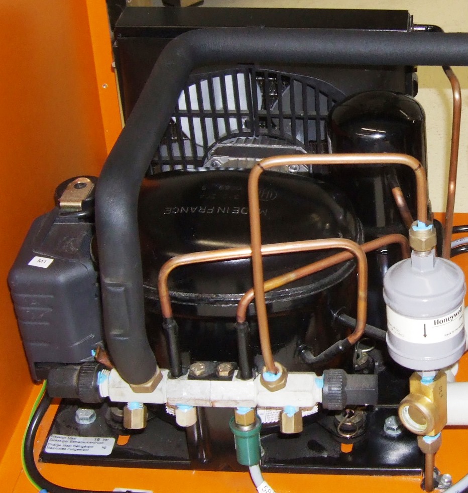
Down to about minus forty, single-stage refrigeration carries the load with ordinary engineering. One compressor, one circuit, common refrigerants, parts in stock within the week. The common rungs at minus ten and minus twenty-five sit well inside this range. General-purpose chambers cluster there.
The step to minus fifty-five or minus sixty-five crosses a thermodynamic boundary. A single circuit runs out of useful pressure ratio. The design moves to a cascade of two refrigeration circuits coupled in series. A cascade works in two stages. The first circuit cools a heat exchanger. The second circuit pulls heat out of that exchanger and sends it to the room. Each circuit runs its own refrigerant, picked for its own range. The pairing reaches a floor a single circuit cannot. The cost, the complexity, and the service profile all rise with it. The lowest rungs come from a heavier build. A parameter change will not stretch a minus forty machine to a minus fifty-five certificate. The cold pushes on the build. Door seals stiffen. They can leak. Insulation has to be thick to hold the gradient. Cable feed-throughs let cold escape. They let frost in.
A chamber can reach minus sixty-five. Under load, it can lose two degrees there. Refrigeration power sets how low a chamber reaches. Holding two degrees there takes power, airflow, and control together. Headroom matters chiefly at the bottom of the range. A machine whose minimum is exactly the test temperature runs the soak at full effort, with nothing in reserve for a warm day or an aging compressor. Specify a minimum a few degrees below the coldest rung you intend to sell. Read a datasheet for the figure the standard limits. The clause is about holding, shown in the uniformity and fluctuation figures, stated at the rung you will sell, under a declared load.
◆Sensor placement and the record
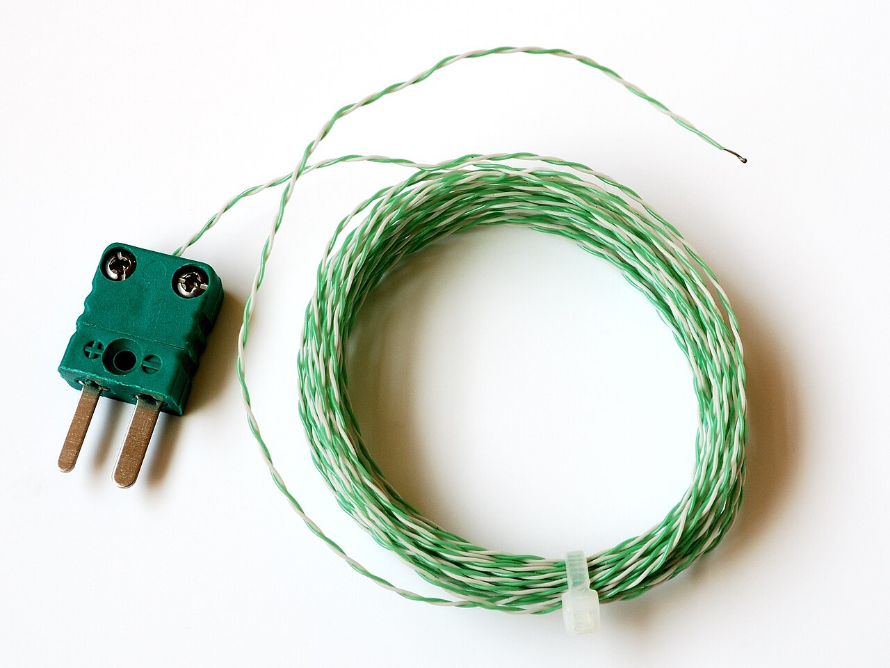
The control sensor runs the loop. It sits at the point the manufacturer tuned around. The proof of the test comes from separate monitoring probes. They sit at the specimen’s position, calibrated against references with current certificates. The rule is to record at the specimen’s representative point, and at the spots mapping has shown to run to the extremes. A single centre probe covers only the centre. The corners need their own probes, or the spatial part of the tolerance stays unproven. The instrumentation belongs on the original order. Calibration runs on an interval. References go to a national standard on a fixed cycle, often a year. Chamber probes are checked against those references. A drifted probe with an out-of-date certificate undoes the record.
The file is what turns hours of cold into a qualification. It holds the trace of the monitored points through descent, soak, and recovery, the calibration certificates, the photograph of the load, and the deviations with their dispositions, signed by someone accountable. The record needs enough resolution to show the movement around defrost and the lowest point of any swing, with timestamps that line up across channels. A reading per channel per minute through the soak, taken more often during descent, keeps the file small enough to store. The detail still answers later questions.
The file outlasts the run. Years later, the people who ran the test have moved on. The record is the only account of what the product saw. A laboratory that builds the file as the test runs passes an audit with little effort. A one-page closing checklist holds the practice together: the trace exported, the certificates attached, the photographs filed, and the signatures collected. The procedure then survives a change of staff.
Recovery closes the test. The standard sets a recovery period before the final measurement, when the product returns to room conditions in still or moving air. A measurement taken too soon gives a wrong cold reading.
◆Where cold sits in the test family
Cold is one test in a large family. IEC 60068 sets out the environmental tests. Test A is cold. Test B is dry heat. Other parts hold the air humid for damp heat, or move the temperature fast for thermal shock. A product’s plan runs the tests its service demands. Cold answers one question: does the product work and survive after time at a low, steady temperature. It says nothing about heat, about humidity, or about a fast change. Those are other tests. A part that has passed Test A has shown it endures the cold. The plan adds the rest as the product’s world asks for them.
◆Questions on cold testing to IEC 60068-2-1
What temperatures does IEC 60068-2-1 use?
The preferred low temperatures run from minus sixty-five up to plus five degrees Celsius. The rungs include minus sixty-five, minus fifty-five, minus forty, minus twenty-five, minus ten, minus five, and plus five, among other values. They pair with soak times of 2, 16, 72, or 96 hours, counted from specimen stability. A specification chooses the pair. The laboratory reaches the rung, proves the specimen has arrived, and holds the band for the stated hours.
How tight is the temperature tolerance in a cold test?
The working figure is about two degrees around the target. It applies across the full working space, for the full soak, on calibrated instruments. Large chambers get a wider band when their size makes two degrees impractical. The strictness is in the reach. The corners count. The defrost movements count. Calibration decides whether a reading counts at all. Mapping surveys keep the band true between calibrations. Disciplined loading keeps it true between surveys.
When does the soak time start counting?
At specimen temperature stability. It does not start when the air display reaches the target. Light specimens follow the air closely. The difference is small there. Dense assemblies lag by hours. The clock waits for them. For heavy products, a laboratory instruments the specimen or an equal thermal dummy and starts the soak timer from that reading. That is the difference between a sixteen-hour test and a sixteen-hour entry in a logbook.
Why is the cooling rate limited?
Because this method tests endurance of low temperature. Survival of rapid change belongs to other methods. The usual average near one degree per minute keeps the specimen descending as one body. It avoids the internal stress of a fast descent. Fast change is the subject of thermal shock and change-of-temperature methods. The limit also keeps results comparable between laboratories. Their plants pull down at widely different speeds.
Can one chamber cover the cold ladder?
Down to about minus forty, ordinary single-stage machines cover the common rungs with margin. The minus fifty-five and minus sixty-five severities need cascade refrigeration, a two-circuit design with its own cost and service character. Laboratories match the fleet to the coldest work they sell. The buying question is the tolerance held in the loaded space at the coldest rung intended, with a few degrees of headroom below it.
What does cold actually do to a product?
It makes materials brittle and slow. A plastic cracks where it would flex when warm. A seal stiffens and leaks. A grease thickens until a mechanism stalls. A battery loses current. A display smears. A board and its joints shrink at different rates. The strain finds a weak joint. The test holds the product at the cold long enough for the slow faults to show, then checks that it still works and survived.
How does cold testing differ from dry heat and thermal shock?
Cold holds a low, steady temperature. Dry heat holds a high one. Thermal shock moves the temperature fast between hot and cold, to stress a part with the speed of the change. Each is a separate test in a separate part of IEC 60068. The cooling rate in a cold test is held slow on purpose, near one degree per minute. The test reads endurance of the cold and leaves the fast change to thermal shock. A product’s plan runs the tests its service asks for.
Why test a product powered on in the cold?
An unpowered soak proves the materials survive the cold. It says nothing about whether the device switches on. A powered cold test holds the product at the low temperature and switches it on cold, the way a car left out overnight starts on a winter morning. A battery weak in the cold, a crystal that drifts, a capacitor that shifts: these show only with power applied at temperature. The procedure names the powered cold start when the product’s service includes it.
Does the soak clock start at the air temperature or the specimen?
At the specimen. The preferred soak times begin when the part itself reaches the cold. They do not begin at the air display. A light part follows the air closely. A dense casting or a potted assembly can lag the air by hours. Starting the clock at the air display gives that part a shorter, easier test than the standard sets. A laboratory testing heavy products puts a probe on the specimen, or on a dummy of the same mass, and starts the timer from that reading.
Envsin builds cold test chambers that hold the IEC 60068-2-1 band from the first rung of the ladder to the cascade bottom.